Installation Guide: Hardware Setup
Overview This guide covers the physical installation of KanexPro Controls products — processors, expanders, keypads, and touch panels. Complete…


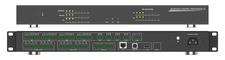 CR-HOST8R
1U AV Control System with 8 Serial, 8 Relay, 8 IR/Serial & 8 Digital I/O
Rack-mount room controller with up to 16 serial connections and open protocol support
Product page →
CR-HOST8R
1U AV Control System with 8 Serial, 8 Relay, 8 IR/Serial & 8 Digital I/O
Rack-mount room controller with up to 16 serial connections and open protocol support
Product page →
This article covers the serial, IR, relay and digital input ports on the CR-HOST8R. It is a 1U control processor with eight COM ports, eight IR/serial outputs, eight relays and eight digital inputs.
COM 1–8 each have a transmit pin, a receive pin and their own TX and RX LEDs, so a device’s responses can come back on the port that sent the command. Match each port’s baud rate and protocol to the controlled device, and confirm the device’s data-bit, parity and stop-bit framing before commissioning. If the device needs a specific framing, confirm with support@kanexpro.com that the CR-HOST8R can match it.
| Pin | Function |
|---|---|
| 1 | RX− (RS-422 and RS-485) |
| 2 | RX+ (RS-422 and RS-485) |
| 3 | TX− (RS-422 and RS-485) |
| 4 | TX+ (RS-422 and RS-485) |
| 5 | GND |
| 6 | TXD (RS-232, with or without flow control) |
| 7 | RXD (RS-232, with or without flow control) |
| 8 | RTS (RS-232 with flow control only) |
| 9 | CTS (RS-232 with flow control only) |
For RS-485, join pin 1 (RX−) to pin 3 (TX−) as B, and pin 2 (RX+) to pin 4 (TX+) as A. For RS-232, connect GND, then wire TXD and RXD to the controlled device according to that device’s own pinout. Every serial port on the CR-HOST8R is a Phoenix terminal rather than a DB9 connector. A device with a DB9 port needs a lead made up from the Phoenix terminal to that device’s pinout.
First, check that the port’s baud rate and protocol (RS-232, RS-422 or RS-485) match the device. Next, check the wiring against the pin-out above. Each COM port has its own TX and RX LEDs on the front panel. TX blinks while the port transmits and RX blinks while it receives. If TX blinks but RX shows no activity, the port is sending and nothing is coming back.
If IR commands do not work, check the IR blaster cable connection and confirm the carrier frequency is within 20–60 kHz. Then re-learn the code through the learning window.
The CR-HOST8R has eight low-voltage relay channels on two 8-pin Phoenix terminals, for lights, doors, curtains and motorized screens. Each relay is an isolated, normally open dry contact rated 2 A at 30 VDC or 1 A at 125 VAC. Wire it into the circuit it switches, with the load powered from that circuit.
Each channel’s yellow relay LED lights when that relay is closed. If a relay does not trigger, check its LED and verify the wiring polarity. Confirm the load is within 2 A at 30 VDC or 1 A at 125 VAC, then test the relay from the web GUI.
The CR-HOST8R runs Android 9 and is configured through its Android interface and open protocols: TCP, UDP, HTTP and WebSocket. Test each relay from the web GUI. For relay programming, contact support@kanexpro.com.
The eight digital I/O channels are inputs only, on two 5-pin Phoenix terminals. They accept dry-contact inputs rated 0–24 V and are intended for sensors. They cannot drive an external device, so use a relay output for that. Each channel’s yellow I/O LED blinks when the signal level at the port changes.
Overview This guide covers the physical installation of KanexPro Controls products — processors, expanders, keypads, and touch panels. Complete…
Overview KanexPro control processors are the central intelligence of an AV control system. They run user-defined scripts, manage event-driven logic…
General What control protocols do KanexPro control processors support? All KanexPro control processors support RS-232 (serial), IR (infrared), relay…
KanexPro sells direct to dealers, resellers, installers and integrators, and through distribution. Whichever way you buy, the same engineers answer the phone.
The trade store: your own account, live stock, reordering, and a first look at new products.
Go to the trade store →Distribution and authorised resellers across the US and beyond.
See where to buy →Design help on extenders, matrix and AV over IP before you spec it.
Ask an engineer →