Downloading KanexPro software and firmware safely
How KanexPro checks firmware and software downloads, how to verify a file's SHA-256 fingerprint, what the Windows SmartScreen warning means, and…


KanexPro control devices communicate over standard IP networks. This article covers IP addressing, PoE power requirements, and network configuration for control system deployments.
All KanexPro control products default to DHCP on first boot. For production installs, static IP addresses are strongly recommended to ensure consistent access for scripting, UI device registration, and third-party control integration.
Assign control devices to a dedicated IP range on your network (e.g., 192.168.10.x) to simplify management and firewall rules. All devices — processor, expanders, keypads, and panels — must be on the same subnet, or inter-VLAN routing must be configured if VLANs are used.
All keypads, touch panels, and expanders are PoE-powered. The control processors (CR-HOST6S, CR-HOST8R) use an included external power supply but include PoE output ports to power downstream devices directly.
| Device | PoE Standard | Max Draw |
|---|---|---|
| CR-KEY8U, CR-KEY10R | IEEE 802.3af (PoE) | ~7W |
| WP-IPKEYPAD8 | IEEE 802.3af (PoE) | ~5W |
| CR-TOUCH4A, CR-TOUCH6R | IEEE 802.3at (PoE+) | ~13W |
| CR-EXPAND1, CR-3XCONTROL | IEEE 802.3af (PoE) | ~7W |
Ensure the PoE switch has sufficient power budget for all connected devices. A 24-port PoE+ switch with 370W budget is typical for medium-to-large deployments.
The control processor listens on specific TCP ports for commands from UI devices and third-party control systems. Default port: 4001 (configurable). Ensure this port is open on any firewall or VLAN ACL between the UI devices and the processor.
The CR-HOST6S includes dual Gigabit PoE output ports. Connect keypads or touch panels directly to these ports — no separate PoE switch required for small deployments with 1–2 UI devices.
Configure DNS on the processor for firmware update access. Configure NTP (time server) to ensure accurate scheduling — the processor’s real-time clock relies on NTP for correct scheduled event execution.
How KanexPro checks firmware and software downloads, how to verify a file's SHA-256 fingerprint, what the Windows SmartScreen warning means, and…
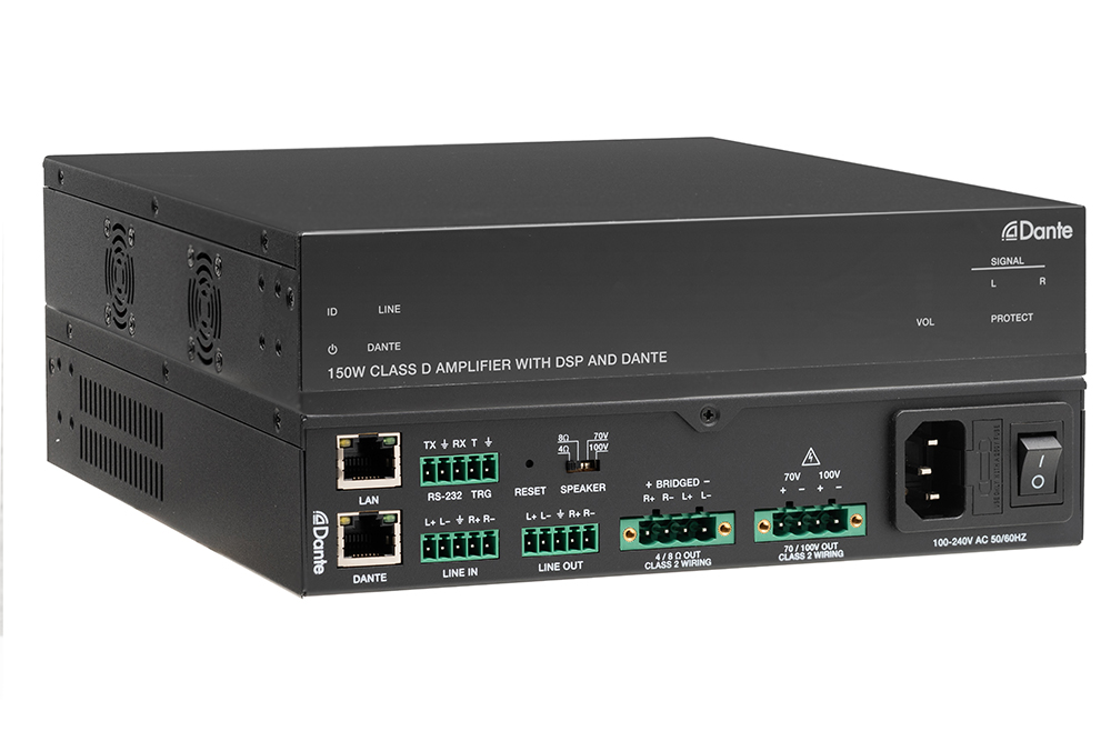
Boardrooms, conference rooms, campuses, lobbies — real-world deployment scenarios Corporate AV is among the most practical deployment target for…
Setup Guide Configuring Your Network Switch for Dante Required switch settings for all KanexPro AUD-DTE- Dante products Dante requires a managed…
KanexPro sells direct to dealers, resellers, installers and integrators, and through distribution. Whichever way you buy, the same engineers answer the phone.
The trade store: your own account, live stock, reordering, and a first look at new products.
Go to the trade store →Distribution and authorised resellers across the US and beyond.
See where to buy →Design help on extenders, matrix and AV over IP before you spec it.
Ask an engineer →