Keep AV over IP Video Off the IT LAN: Spec a Dual-Port Controller
Don't run AV over IP video on the building network. Put endpoints on their own switch and use a controller with a separate port for IT control.


One way to wire a control job is to bring everything back to the processor. The display gets a serial cable pulled back to the rack. The projector gets an IR emitter lead, extended through the ceiling. The screen and the lighting each get a pair of contact-closure wires. The occupancy sensor gets one more pair. Each one is a separate pull, with terminations at both ends and a label that has to survive the job.
We think that habit is worth dropping. Pull one network drop to the place where the devices are, and put the serial, IR, relay and sensor ports there. The processor reaches them over the network it already uses. The long run becomes ordinary Ethernet, and the short, fussy signals stay short.
Think about what home-running means over the life of a room. Moving a display means re-pulling its serial line. Adding a motorised screen means finding a path for two more conductors. When something stops responding, you have to trace a cable through a ceiling you can no longer see into, and the trouble could be at either end.
Serial, IR and dry contacts are local signals. RS-232 was designed as a point-to-point link between nearby devices. An IR emitter is a small LED stuck over a sensor window. A relay contact is simply open or closed. None of them gets better from travelling across a building, and every extra joint is one more place for a fault.
Ethernet was designed for the long run, and the control processor already speaks it. If the control endpoint sits at the device, the processor sends a command over IP and the endpoint turns it into serial bytes, an IR burst or a relay closure a short lead away from where it lands. With PoE, the same cable powers the endpoint, so you don't need an outlet behind the display just for control.
Troubleshooting improves as well. Instead of a cable whose condition you can only guess at, you have an addressable box with status lights and a web page. You can check it from your laptop before you get the ladder out.
The CR-EXPAND1 is built for exactly this layout. Its one RJ45 port is 100M Ethernet that also accepts PoE, and the unit draws 0.96W. On the same small housing (95 × 68 × 17 mm, with two mounting ears) it carries:
The manual's typical setup shows the pattern: a control processor sends TCP/UDP API commands through a PoE switch to the expander. The expander controls a display over serial and a projector by IR blaster, raises the screen on relay 1, switches lighting on relay 2 and reads an occupancy sensor on the digital input.
On the network side, system commands use TCP port 8000 and serial data uses TCP port 8001. Serial data passes both ways between the COM port and the network port, so the processor can read replies from the display, not just send to it. ASCII commands end in an exclamation mark, such as set relay1:on!, and hex commands are also accepted for every function. A built-in web server handles setup without special software. Front-panel LEDs for Power, TX, RX, I/O, IR, Relay 1 and Relay 2 show at a glance what the box is doing.
Home-running is still correct when the device sits in the rack beside the processor. A short patch from a spare processor port is simpler than adding another network endpoint.
Count your ports before you count on one box per location. This unit has one serial port and one IR output. Two serial-controlled displays behind one wall, or two IR-only sources on one shelf, need more than one expander or a different plan.
Respect the relay rating. At 30VDC 1A / 125VAC 0.3A, these relays are for low-voltage contact closures, such as a screen's control input or a lighting system's trigger. They are not for switching motor or lighting power directly.
Finally, check the environment and the network. The unit is rated to operate from 0°C to 40°C, in non-condensing humidity. If the site's IT policy will not put control endpoints on its network, and there is neither PoE nor local DC power, the endpoint has nowhere to live.
No. It works with any IP-based control system over TCP or UDP. Its built-in web server and API also let it run on its own, with no central processor.
Yes. The IR output and the RS-232/RS-485 port are independent, so one expander can control a serial display and an IR-only projector together.
They can trigger one through a low-voltage control input. Each relay is normally open and switches up to 30V DC at 1A or 125V AC at 0.3A, which suits contact closures for screens, lighting, curtains and access control.
Yes. Connect a DC 12–24V/1A supply to the DC IN connector. It draws under 1W.
There is no fixed limit. Each unit has its own IP address and is managed independently, so every display location can have one.
Hold the RESET button on the rear panel for 5 seconds, or use Factory Reset on the web GUI's System page. The unit reboots to its defaults, including the address 192.168.0.101.
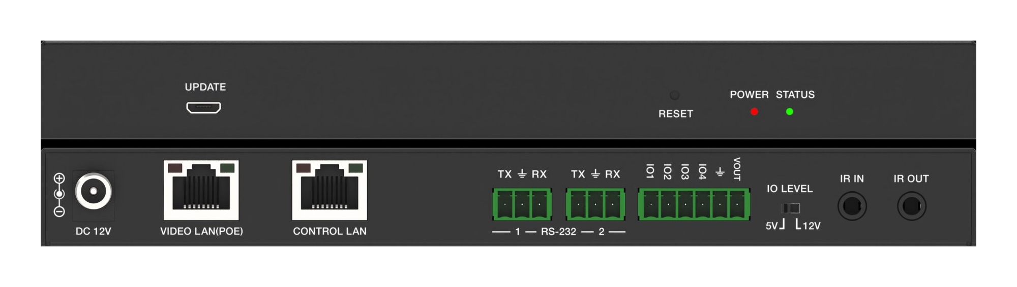
Don't run AV over IP video on the building network. Put endpoints on their own switch and use a controller with a separate port for IT control.
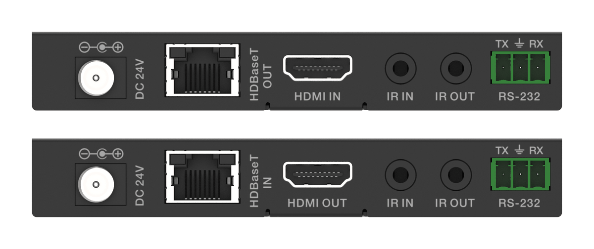
How the EXT-HDBT18G-70M carries 4K60 HDR, IR and RS-232 over one CAT6 with power at one end, and where it fits in rooms, venues and signage.
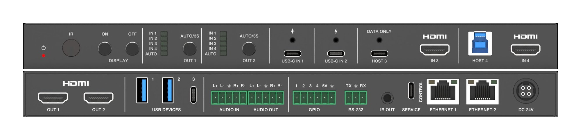
Two displays in a huddle room should show two things. A 4x2 matrix lets each screen pick its own source, so the room stops showing one laptop twice.
KanexPro sells direct to dealers, resellers, installers and integrators, and through distribution. Whichever way you buy, the same engineers answer the phone.
The trade store: your own account, live stock, reordering, and a first look at new products.
Go to the trade store →Distribution and authorised resellers across the US and beyond.
See where to buy →Design help on extenders, matrix and AV over IP before you spec it.
Ask an engineer →