Overview
KanexPro JPEG2000 AV over IP drives video walls from the AVO-IPCTL-JP2K system controller. The controller manages up to 9 independent video walls per system, each from 1×2 up to 9×9 (81 displays), over a 1G managed network. Every display has its own JPEG2000 decoder and every source its own encoder. Walls are built, border-adjusted and switched in the controller's web GUI. This note covers equipment, network preparation, controller setup and control-system integration for a wall deployment.
Supported Configuration
- Wall size: 1×2 up to 9×9 (81 displays) per wall
- Walls per system: up to 9, which can be different sizes; each decoder can be assigned to only one wall
- Class Presets: up to 9 per wall; screens that share a class name form one video wall group, regular or irregular
- Per-display resolution: JPEG2000 decoders output up to 4K60 4:4:4
- Bezel correction: Border Adjustment per decoder (Base Width, Image Width, Base Height, Image Height)
- System size: encoder IDs and decoder IDs each range from 1 to 762
Equipment Required
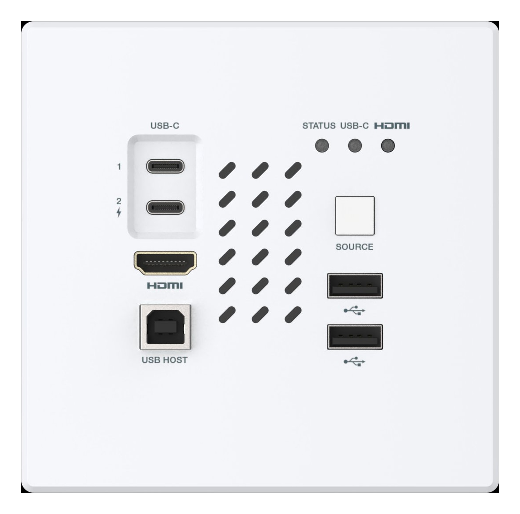
- One JPEG2000 encoder per source: AVO-IPJP2K-ENC (copper plus SFP fiber), AVO-IPJP2KS-ENC (slim, PoE), AVO-IPJP2KD-ENC (Dante dual LAN) or the AVO-IPJP2KWPM wall plate
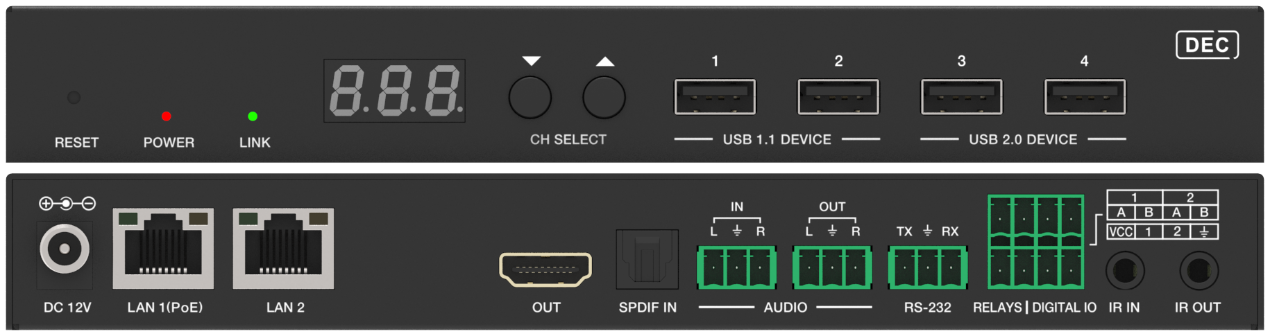
- One JPEG2000 decoder per display: AVO-IPJP2K-DEC, AVO-IPJP2KS-DEC or AVO-IPJP2KD-DEC
- One AVO-IPCTL-JP2K controller
- A Layer-3 managed gigabit switch with IGMP snooping and 8K jumbo frames. The endpoint manuals list the Cisco SG500, Cisco Catalyst series, Huawei S5720S-28X-PWR-LI-AC, ZyXEL GS2210 and Luxul AMS-4424P.
- Network cable within 100 m per endpoint: CAT5e/6/6A/7 for the AVO-IPJP2K-ENC and AVO-IPJP2K-DEC; CAT6/6A/7 for the AVO-IPJP2KS-ENC, AVO-IPJP2KS-DEC, AVO-IPJP2KD-ENC, AVO-IPJP2KD-DEC and AVO-IPJP2KWPM
Step-by-Step Setup
1. Network Preparation
- Enable IGMP snooping on the AV switch.
- Enable 8K jumbo frames on the AV switch.
- If the switch supplies PoE, check that its PoE budget covers the controller and every endpoint at once. Without PoE, power the controller from its DC 12V/1A adapter and each encoder and decoder from its DC 12V/2.5A adapter.
2. Physical Installation
- Connect each display to its decoder's HDMI OUT and each source to its encoder's HDMI IN. On the AVO-IPJP2K-ENC and AVO-IPJP2K-DEC, HDMI cable length is rated to 5 m at 4K60, 10 m at 4K30 and 15 m at 1080p60.
- Connect every encoder and decoder to the AV switch. On the AVO-IPJP2K-ENC and AVO-IPJP2K-DEC you can use the SFP fiber slot instead, but transport defaults to copper and must be set to fiber on the unit or in the controller.
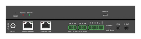
- Connect the controller's VIDEO LAN port to the same AV switch.
- Connect the controller's CONTROL LAN port to the IT network or a PC. It must not be left unconnected, even in a single-switch installation.
- Label each decoder with its wall position (R1C1, R1C2 and so on) as you mount it. The controller lets you name each decoder (up to 16 characters, no special characters) and set its ID.
3. Controller First-Time Setup
- Browse to http://controller.local. With no DHCP server on the control network, the CONTROL LAN falls back to 192.168.6.100; set the PC to the same subnet (for example 192.168.6.88).
- Log in with the default admin / admin and set a new password when prompted: 6–8 alphanumeric characters, no special characters.
- In the setup wizard, choose the Video LAN IP mode: Auto (the controller assigns addresses; recommended for new installs), DHCP or Static. In Static mode the encoders and decoders must be in the Video LAN subnet.
- Let discovery finish, then add the encoders and decoders automatically or one at a time. Search Device Via Wizard on the Device page re-runs discovery later.
- On the Device page, name and number each decoder to match its wall position.
4. Build the Video Wall
- Create: on the Video Wall page, click Create, set the Video Wall ID, name, row count and column count, then click Go.
- Assign Decoder: select the wall, click Assign Decoder, click each screen position and choose the decoder mounted there, then click Apply.
- Class Preset: click Class Preset and give each screen a class name. Screens that share a class name form one video wall group, which can be regular or irregular. Click Apply. Each wall holds up to 9 presets, named with up to 16 letters or numbers.
- Border Adjustment: set Base Width, Image Width, Base Height and Image Height for each decoder, then click Apply for one decoder or Apply All. A Base value cannot exceed twice its Image value.
- Source: on the Video Wall Source tab, drag an encoder onto the wall. Offline encoders cannot be dragged to a wall.
Switching Video Wall Sources
In the web GUI, drag a different encoder onto the wall on the Video Wall Source tab. Use the VW/Pre icons to move between walls and presets, and drag No Source onto a wall to disconnect it.
From a control system, connect a Crestron, AMX, QSC or other processor to one of the controller's two RS-232 ports (3-pin 3.81 mm Phoenix) or over TCP/IP on the CONTROL LAN. Its API covers matrix switching, video wall preset recall, source switching and GPIO automation. Ask KanexPro technical support for the command set before you write the control program. Control methods are Web GUI, TCP/IP, RS-232, IR, SSH, SFTP and HTTPS. Telnet and SSH can each be turned on or off, with their ports set, under Controller Settings.
Best Practices
- If a wall does not display as expected, check that IGMP snooping and 8K jumbo frames are on, that every endpoint shows online on the Device page, that the correct layout is applied and that every decoder is assigned.
- Before assigning a source to a wall, confirm the encoder has a signal in its MJPEG preview on the Device or Matrix page.
- To swap a failed decoder without losing its routing configuration, use Replace on the Device page. Unplug the offline unit, connect the replacement, then click Replace, Scan for Devices, select it and click Replace.
- Once the wall is commissioned, save the system configuration to a JSON file under Controller Settings > System Configurations. Load restores it.
Video Wall Questions
How large can a JPEG2000 video wall be?
Each wall can be anything from 1×2 up to 9×9, which is 81 displays. One AVO-IPCTL-JP2K system holds up to 9 walls of different sizes, and each decoder can belong to only one of them.
Is the controller required for a video wall?
Yes. Point-to-point unicast works without it, but matrix switching, video walls and KVM roaming all need the AVO-IPCTL-JP2K.
Can a JPEG2000 wall include H.265 or SDVoE endpoints?
No. The AVO-IPCTL-JP2K manages JPEG2000 endpoints only; it can manage Gen 1 and Gen 2 JPEG2000 units in one system. H.265 systems use the AVO-IPCTL-265, and SDVoE systems use the AVO-IPCTL-SDV.
Why does the controller not find my decoders?
Check that the VIDEO LAN port and every encoder and decoder are on the same managed switch, and that IGMP snooping is enabled. In Static mode, also confirm the endpoint addresses are inside the Video LAN subnet. Then run Search Device Via Wizard from the Device page.
Related Articles
- Getting Started with AV over IP
- Network Setup for AV over IP
- JPEG2000 Product Guide
- Troubleshooting: No Signal Between Encoder and Decoder


 AVO-IPCTL-JP2K
4K60 JPEG2000 AV over IP System Controller
Centralized Matrix Switching, 9×9 Video Wall & KVM Roaming for JPEG2000 AV over IP Systems —…
Product page →
AVO-IPCTL-JP2K
4K60 JPEG2000 AV over IP System Controller
Centralized Matrix Switching, 9×9 Video Wall & KVM Roaming for JPEG2000 AV over IP Systems —…
Product page →