Overview
This guide covers physical installation of KanexPro AV over IP encoders and decoders: mounting, cabling, power, first power-on and link checks. It concentrates on the JPEG2000 family, including the AVO-IPJP2KWPM wall plate encoder. Finish this stage before you configure the network or routing.
What You Need
- Encoders (one per source) and decoders (one per display) from the same codec family
- HDMI cables. On the AVO-IPJP2K-ENC, AVO-IPJP2K-DEC and AVO-IPJP2KD-ENC, HDMI length is rated to 5 m at 4K60, 10 m at 4K30 and 15 m at 1080p60.
- Network cable of the category rated for each model (see the table below)
- A managed switch. JPEG2000 endpoints need a Layer-3 managed gigabit switch with IGMP snooping and 8KB jumbo frames; see Compatibility & Interoperability: Recommended Managed Switches.
- Power for each unit: PoE from the switch (the JPEG2000 endpoints are PoE powered devices) or a local DC 12V/2.5A adapter. Check each model's package contents, because the AVO-IPJP2KS-DEC lists its adapter as optional.
Cabling Requirements
Step-by-Step: Encoder Installation
- Mount the encoder near the source. The AVO-IPJP2K-ENC, AVO-IPJP2K-DEC, AVO-IPJP2KS-ENC, AVO-IPJP2KS-DEC, AVO-IPJP2KD-ENC and AVO-IPJP2KD-DEC ship with mounting ears or brackets, and their manuals cover a 6U V2 rack (6, 8 or 10 units vertically) or two units side by side in a 1U V2 rack. The V2 rack is bought separately.
- Connect the source to HDMI IN.
- For USB KVM, connect the encoder's USB HOST (Type B) port to the source computer.
- Connect the LAN (PoE) port to the switch. On the AVO-IPJP2KD-ENC this is LAN 1; in the default LAN Mode 2, LAN 2 carries Dante audio.
- If the switch does not supply PoE, connect the DC 12V/2.5A adapter.
Step-by-Step: Decoder Installation
- Mount or place the decoder near the display.
- Connect the decoder's HDMI OUT to the display.
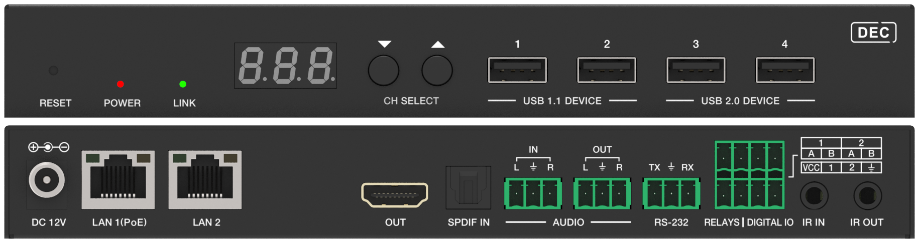
- For USB KVM, connect the keyboard and mouse to the decoder's USB device ports. On the AVO-IPJP2K-DEC, the USB 1.1 port takes a keyboard or mouse and the two USB 2.0 ports take devices such as a flash drive or USB camera.
- Connect the LAN (PoE) port to the switch, or on the AVO-IPJP2K-DEC use the FIBER slot.
- If the switch does not supply PoE, connect the DC 12V/2.5A adapter.
Wall Plate Encoder: AVO-IPJP2KWPM
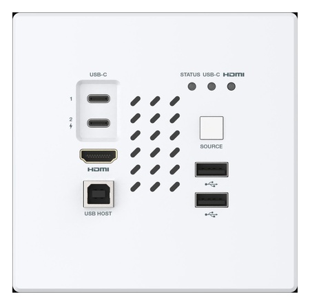
The AVO-IPJP2KWPM is a JPEG2000 BYOD encoder in a US 2-gang wall plate. Its magnetic-attachment panel snaps in without tools.
- Wall box: US 2-gang. The unit measures 4.56 × 4.50 × 1.74 in (115.9 × 114.3 × 44.25 mm), so confirm the box has the depth.
- Network: 1× LAN/PoE RJ45 to the managed 1G switch, over CAT6, CAT6A or CAT7 up to 100 m (328 ft)
- Power: PoE (802.3af PD) from the switch, or the included DC 12V/2.5A multinational supply
- Inputs: HDMI IN (Type A); USB-C IN 1 carries video, audio and USB data from the laptop; USB-C IN 2 provides PD charging to the source device, up to 100W. HDMI and USB-C switch automatically.
- Audio: 1× audio IN and 1× audio OUT, unbalanced, on 3-pin 3.5 mm Phoenix. Audio return is analog only.
- Control and USB: 1× RS-232 on 3-pin 3.5 mm Phoenix; 1× USB 2.0 HOST (Type B); 2× USB 2.0 DEVICE (Type A)
- In the box: the encoder wall plate, 3× 3-pin 3.5 mm Phoenix connectors, the DC 12V/2.5A multinational supply and a user manual
It is an encoder only: pair it with a JPEG2000 decoder such as the AVO-IPJP2K-DEC, AVO-IPJP2KS-DEC or AVO-IPJP2KD-DEC. Matrix switching and video walls up to 9×9 need the AVO-IPCTL-JP2K controller.
How is the AVO-IPJP2KWPM powered?
By PoE (802.3af PD) on its RJ45 LAN port, or by the DC 12V/2.5A multinational supply that ships with it. Use the supply where the switch port does not deliver PoE.
What network cable does the AVO-IPJP2KWPM need?
CAT6, CAT6A or CAT7, up to 100 m (328 ft) to a managed 1G switch. Plan the run on one of those cable types rather than CAT5e.
How does the AVO-IPJP2KWPM mount?
It fits a US 2-gang wall box, and its magnetic-attachment front panel snaps in without tools. Use the user manual in the box for the mounting hardware and sequence.
Fiber on the AVO-IPJP2K-ENC and AVO-IPJP2K-DEC
Both units have a copper LAN port and an SFP optical slot in one box. Transport defaults to copper (CPP), so a fiber install must be switched to fiber (FIB) on the front-panel Fiber/Copper page, or set to Fiber under Network Interface on the AVO-IPCTL-JP2K Device page. The AVO-IP265-4K works differently: copper has priority when both are connected, and the unit switches to fiber when the copper cable is removed.
Verifying Link Status
On the JPEG2000 encoders and decoders:
- POWER LED (red): on means the unit has power, from PoE or DC; off means no power
- LINK LED (green): on means the encoder and decoder are linked and video is passing; flashing means linked but no video; off means not linked
- RJ45 indicators: green is on when the network cable is connected; yellow flashes with data traffic
A flashing LINK LED on an AVO-IPJP2K-ENC means the input signal is missing or incompatible. Keep the source within 4K60 4:4:4 (HDMI 2.0b, HDCP 2.2) and reseat the HDMI IN cable.
First Power-On
JPEG2000 endpoints ship in Auto IP mode on the 169.254.x.x segment. The static defaults are 169.254.100.254 for encoders and 169.254.100.253 for decoders. To reach a unit directly, connect a PC to the same switch, set it to the same segment and find the unit with a Bonjour/mDNS discovery tool such as zeroconfServiceBrowser. On the AVO-IPJP2K-ENC and AVO-IPJP2K-DEC, host names start with AST-ENC and AST-DEC. On units with a front-panel screen, hold UP for 5 seconds to display the current IP address. With an AVO-IPCTL-JP2K in its default Auto mode, the controller assigns addresses and discovers the endpoints. To factory-reset a JPEG2000 endpoint, hold RESET after power-on until the POWER and LINK LEDs flash together, then release.
Related Articles